دوائر التوازي الكهربائيةParallel Circuits
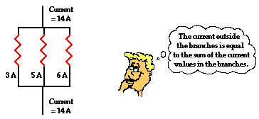
In equation form, this principle can be written as
where Itotal is the total amount of current outside the branches (and in the battery) and I1, I2, and I3 represent the current in the individual branches of the circuit.
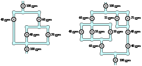
Throughout this unit, there has been an extensive reliance upon the analogy between charge flow and water flow. Once more, we will return to the analogy to illustrate how the sum of the current values in the branches is equal to the amount outside of the branches. The flow of charge in wires is analogous to the flow of water in pipes. Consider the diagrams below in which the flow of water in pipes becomes divided into separate branches. At each node (branching location), the water takes two or more separate pathways. The rate at which water flows into the node (measured in gallons per minute) will be equal to the sum of the flow rates in the individual branches beyond the node. Similarly, when two or more branches feed into a node, the rate at which water flows out of the node will be equal to the sum of the flow rates in the individual branches that feed into the node.
The same principle of flow division applies to electric circuits. The rate at which charge flows into a ![]() node is equal to the sum of the flow rates in the individual branches beyond the node. This is illustrated in the examples shown below. In the examples a new circuit symbol is introduced - the letter A enclosed within a circle. This is the symbol for an ammeter - a device used to measure the current at a specific point. An ammeter is capable of measuring the current while offering negligible resistance to the flow of charge.
node is equal to the sum of the flow rates in the individual branches beyond the node. This is illustrated in the examples shown below. In the examples a new circuit symbol is introduced - the letter A enclosed within a circle. This is the symbol for an ammeter - a device used to measure the current at a specific point. An ammeter is capable of measuring the current while offering negligible resistance to the flow of charge.
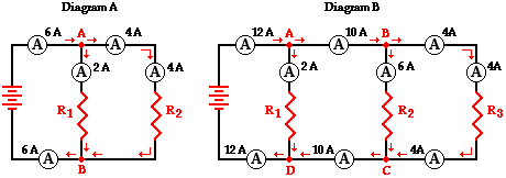
Diagram A displays two resistors in parallel with nodes at point A and point B. Charge flows into point A at a rate of 6 amps and divides into two pathways - one through resistor 1 and the other through resistor 2. The current in the branch with resistor 1 is 2 amps and the current in the branch with resistor 2 is 4 amps. After these two branches meet again at point B to form a single line, the current again becomes 6 amps. Thus we see the principle that the current outside the branches is equal to the sum of the current in the individual branches holds true.
6 amps = 2 amps + 4 amps
Diagram B above may be slightly more complicated with its three resistors placed in parallel. Four nodes are identified on the diagram and labeled A, B, C and D. Charge flows into point A at a rate of 12 amps and divides into two pathways - one passing through resistor 1 and the other heading towards point B (and resistors 2 and 3). The 12 amps of current is divided into a 2 amp pathway (through resistor 1) and a 10 amp pathway (heading toward point B). At point B, there is further division of the flow into two pathways - one through resistor 2 and the other through resistor 3. The current of 10 amps approaching point B is divided into a 6-amp pathway (through resistor 2) and a 4-amp pathway (through resistor 3). Thus, it is seen that the current values in the three branches are 2 amps, 6 amps and 4 amps and that the sum of the current values in the individual branches is equal to the current outside the branches.
12 amps = 2 amps + 6 amps + 4 amps
A flow analysis at points C and D can also be conducted and it is observed that the sum of the flow rates heading into these points is equal to the flow rate that is found immediately beyond these points.
Equivalent Resistance
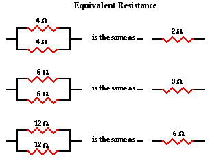
The actual amount of current always varies inversely with the amount of overall resistance. There is a clear relationship between the resistance of the individual resistors and the overall resistance of the collection of resistors. To explore this relationship, let"s begin with the simplest case of two resistors placed in parallel branches, each having the same resistance value of 4 Ω. Since the circuit offers two equal pathways for charge flow, only one-half the charge willchoose to pass through a given branch. While each individual branch offers 4 Ω of resistance to any charge that flows through it, only one-half of all the charge flowing through the circuit will encounter the 4 Ω resistance of that individual branch. Thus, as far as the battery that is pumping the charge is concerned, the presence of two 4-Ω resistors in parallel would be equivalent to having one 2-Ω resistor in the circuit. In the same manner, the presence of two 6-Ω resistors in parallel would be equivalent to having one 3-Ω resistor in the circuit. And the presence of two 12-Ω resistors in parallel would be equivalent to having one 6-Ω resistor in the circuit.
Now let"s consider another simple case of having three resistors in parallel, each having the same resistance of 6 Ω. With three equalpathways for charge to flow through the external circuit, only one-third the charge will choose to pass through a given branch. Each individual branch offers 6 Ω of resistance to the charge that passes through it. However, the fact that only one-third of the charge passes through a particular branch means that the overall resistance of the circuit is 2 Ω. As far as the battery that is pumping the charge is concerned, the presence of three 6-Ω resistors in parallel would be equivalent to having one 2-Ω resistor in the circuit. In the same manner, the presence of three 9-Ω resistors in parallel would be equivalent to having one 3-Ω resistor in the circuit. And the presence of three 12-Ω resistors in parallel would be equivalent to having one 4-Ω resistor in the circuit.
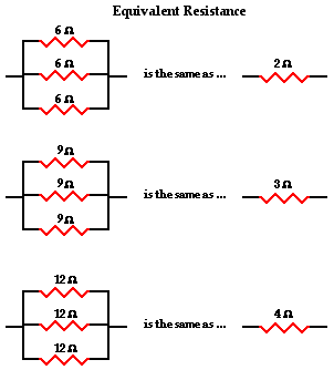
This is the concept of equivalent resistance. The equivalent resistance of a circuit is the amount of resistance that a single resistor would need in order to equal the overall effect of the collection of resistors that are present in the circuit. For parallel circuits, the mathematical formula for computing the equivalent resistance (Req) is
where R1, R2, and R3 are the resistance values of the individual resistors that are connected in parallel. The examples above could be considered simple cases in which all the pathways offer the same amount of resistance to an individual charge that passes through it. The simple cases above were done without the use of the equation. Yet the equation fits both the simple cases where branch resistors have the same resistance values and the more difficult cases where branch resistors have different resistance values. For instance, consider the application of the equation to the one simple and one difficult case below.
|
1/Req = 1/(12 Ω) + 1/(12 Ω) + 1/(12 Ω) Using a calculator ... 1/Req = 0.25 Ω-1 Req = 1 / (0.25 Ω-1) Req = 4.0 Ω
|
|
1/Req = 1/(5.0 Ω) + 1/(7.0 Ω) + 1/(12 Ω) Using a calculator ... 1/Req = 0.42619 Ω-1 Req = 1 / (0.42619 Ω-1) Req = 2.3 Ω |


